UHF Crystal Radio

A crystal radio was wired up to check for reception of VHF/UHF signals in the vicinity of the shack.

VHF / UHF Crystal Radio - Schematic
Using a gold bonded Germanium diode 1N65, a 500 mm whip antenna and balanced-armature phones, no signals were audible either in the shack or on the shack roof.

However, using a 250 mm whip, a weak digital signal was detected while moving on the shack roof. Position on the roof and direction in which the whip was pointed were quite critical.

It was presumed that the signals were from a nearby cellphone tower.

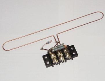
A 3 Element Yagi Beam for 33 cm was made using a broken snare drum stick for the boom and 20 SWG bare copper wire for the elements.

UHF Yagi Beam Crystal Radio  - Schematic
The coil was wound integral with the driven element. 

UHF Yagi Beam Crystal Radio
With this setup a higher signal strength was obtained.

A second Yagi Beam was then rigged up, with another diode providing the return path for the audio, instead of the coil.

UHF Yagi Beam Crystal Radio
with additional diode - Schematic
The signal strength was not as good. During trials, a chance shorting of  the first diode gave a considerable increase in signal strength.

Single-diode UHF Yagi Beam
Crystal Radio - Schematic
The diode and capacitor were hence discarded. Performance of this single-diode UHF crystal radio is quite good.
Single-diode UHF Yagi Beam Crystal Radio
A folded dipole version, mounted on a terminal block, followed.

UHF Folded Dipole Crystal Radio - Schematic
It obviated the need for a coil / additional diode and worked quite well too.

UHF Folded Dipole Crystal Radio
The terminal block arrangement made it convenient to replace the folded dipole with a full wave loop.
UHF Full Wave Loop Crystal Radio
Likewise with an AWX antenna.

UHF AWX Antenna Crystal Radio
Results were as good as with the folded dipole.

Related post: Minimalist UHF Crystal Radio
_______________________________

Series-tuned Ferrite Loopstick Crystal Radio

This series-tuned crystal radio is housed in a plastic pencil box.

Series-tuned Ferrite Loopstick 
Crystal Radio
It has 2 windings of 30 SWG enamelled copper wire on a 6" long, 3/8 " diameter ferrite rod. The primary has 10 turns and the secondary 90, both close-wound.

Series-tuned Ferrite Loopstick
Crystal Radio - schematic
The primary series-tuned circuit, which includes the 200μH moulded inductor, the 3600 pf capacitor and the capacitance of the 60' wire antenna, is resonant at 612 kHz (the frequency of the local 200 kW station, located 20km away). The secondary is also series-tuned using a 500pf PVC variable capacitor. The detector, a germanium transistor with its base and emitter connected, shunt-feeds sensitive balanced-armature phones. Reception of the local station is quite good, with a headphone current of 625 μA (measured using a 1mA FSD 60 Ω meter).

Series-tuned Ferrite Loopstick
Crystal Radio - inside view
Reception is as good without an external antenna and earth, when the radio is held close to a CATV cable running over the shack and working as a passive radiator. Signal strength is maximum when the ferrite rod is laterally oriented with respect to it (with headphone current measuring around 350 μA).

This radio also works quite well, even up to 5 km away from the transmitter, unaided by external antennas, earth and passive radiators.

Related post: Series-tuned Air-core Coil Crystal Radio
_______________________________