Crystal Radio Output Transformer

The large size of the power transformer, used as an output transformer for my 'Loudspeaker 
Crystal Radio', was good enough reason to attempt homebrewing a relatively small one.

A search through the junk box yielded a 47mm diameter, Siemens N22 pot core set.

Pot Core used for Crystal Radio Output Transformer
Winding was for an autotransformer, having 500 turns of 30 SWG enamelled copper wire (the maximum number that could be accommodated), with output taps at 50 and 100 turns.


Crystal Radio Output Transformer - winding scheme
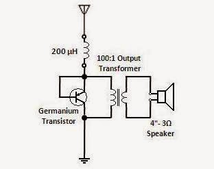
The 50-turn tap was to match the existing 3 Ω speaker and the100-turn one a provision for speakers of higher impedance.

A small PCB, also from the junk box, provided termination points for the winding.

Crystal Radio Output Transformer- inside view
A couple of reworked white plastic cosmetic jar bodies lent themselves as enclosure halves.

Crystal Radio Output Transformer
Tests indicated that, inspite of its small size, the output transformer's performance is comparable, though not equal, to that of the power transformer.

_______________________________

Colourful Parallel-tuned Air-core Coil Crystal Radio

This is the colourful version of my 'Parallel-tuned Air Core Coil Crystal Radio'.

Colourful Crystal Radio
The coil is 75turns of hook-up wire, close-wound on a 2 ⅝" diameter plastic bottle, with a tap at 35 turns.

The 35 turn primary series-tunes the capacitive 60' wire antenna to resonance at 612kHz (frequency of the lone 200kW local AM broadcast station). The secondary is parallel-tuned using a 500+500 pF PVC gang condenser.

Colourful Crystal Radio - Schematic
The plastic bottle serves as the coil former cum enclosure. A screw-type terminal strip is used to connect antenna, earth and headphones.

Reception, using sensitive balanced-armature headphones, is quite good. Headphone current, measured using a 1mA FSD 60 Ω meter, is 400 μA.

Related post: Parallel-tuned Ferrite Toroid Crystal Radio
_______________________________

Parallel-tuned Ferrite Toroid Crystal Radio

This is the toroid coil variant of my 'Ferrite Loopstick Crystal Radio'.

Parallel-tuned Ferrite Toroid Crystal Radio
A ferrite toroid, measuring OD 16.5mm, ID 10.5mm and H 10.5mm, is used. The coil is 25 turns of hook-up wire with a tap at 5 turns. On the primary side, a 200μH moulded inductor series-tunes the capacitive 60' long wire antenna to resonance at 612kHz (frequency of the lone 200kW local AM broadcast station). The secondary is parallel-tuned using a PVC gang condenser.

Parallel-tuned Ferrite Toroid Crystal Radio - Schematic
A small plastic trinket box serves as the enclosure. A screw-type terminal strip is used to connect antenna, earth and headphones.

Rear of Crystal Radio with Ferrite Toroid Coil
Reception, using sensitive balanced-armature headphones, is quite good. Headphone current, measured using a 1mA FSD 60 Ω meter, is 275 μA.

Related post: Parallel-tuned Air-core Coil Crystal Radio
_______________________________

Parallel-tuned Air-core Coil Crystal Radio

This is the air-core-coil variant of my 'Ferrite Loopstick Crystal Radio'.

Parallel-tuned Air-core Coil Crystal Radio
The coil is 72 turns of 30 SWG enamelled copper wire, close-wound on a 2½" length of 2" diameter PVC pipe, with a tap at 12 turns.

The primary winding, along with the 200μH moulded inductor and 1000 pf capacitor, series-tunes the capacitive 60' wire antenna to resonance at 612kHz (frequency of the lone 200kW local AM broadcast station). The secondary is parallel-tuned using a PVC gang condenser.

Parallel-tuned Air-cor Coil Crystal Radio Schematic
One half of an acrylic trinket box serves as the base/enclosure. A screw-type terminal strip is used to connect antenna, earth and headphones.

Reception, using sensitive balanced-armature headphones, is quite good. Headphone current, measured using a 1mA FSD 60 Ω meter, is 350 μA.

Related post: Ferrite Loopstick Crystal Radio
_______________________________

Ferrite Loopstick Crystal Radio

Here's my version of a ferrite loopstick crystal radio.

Parts used are a moulded inductor, a 2200pf capacitor, a MW loopstick antenna, a PVC gang condenser and a germanium diode. The enclosure is a 3" x 3" x 1½" electrical bakelite box.

Ferrite Loopstick Crystal Radio
Ferrite Loopstick Crystal Radio - Schematic
Screw terminals are provided on the rear of the enclosure for connecting the antenna, earthand headphones. Headphones used are of the sensitive, balanced-armature type.

Inside the Ferrite Loopstick Crystal Radio
The loopstick is 125 turns of Litz wire close-wound on a 2" length of ferrite rod with a tap at 25 turns. The number of turns may vary depending on the diameter of the ferrite rod and its relative permeability.

The primary series-tuned circuit consists of the 200μH moulded inductor, the 2200 pf capacitor and the capacitance of the 60' wire antenna. The secondary is parallel-tuned.        

Reception of the local 612 kHz, 200 kW AM broadcast station is quite good. Headphone current, measured using a 1mA FSD 60 Ω meter, is 300 μA.

Reception is as good without an external antenna and earth, when the radio is held close to a CATV cable running over the shack and working as a passive radiator. Signal strength is maximum when the ferrite rod is laterally oriented with respect to it.

Related: Permeability-tuned Crystal Radio
_______________________________

Permeability-tuned Crystal Radio

This simple, permeability-tuned crystal radio was wired using a variable inductor, a germanium diode/transistor and a pair of sensitive DLR No.5 I.T.B.A.5 S balanced-armature headphones.
 
Permeability-tuned Crystal Radio 
A germanium diode was used as the detector in the series-fed version.     

Permeability-tuned, Series-fed
Crystal Radio - Schematic
 For the shunt-fed version it was a germanium transistor (with its base and emitter interconnected). 

Permeability-tuned, Shunt-fed 
Crystal Radio - Schematic
An empty glue stick and a ferrite toroid were used for the tuning mechanism.

The toroid was fixed to the blue glue stick carrier using rubber adhesive. The coil was 60 turns of 30 SWG enamelled copper wire, close-wound on a homebrewed 1" diameter paper former which fit tightly on the glue stick body.

Tuning mechanism for
Permeability-tuned Crystal Radio
Junk-box parts were used to assemble and wire the radio using a scrap wall wart enclosure as the base.

Reception of  the local 612 kHz, 200 kW AM broadcast station was quite good, with just a 60' wire antenna. Headphone current, measured using a 1mA FSD 60 Ω meter, was 350 μA.

During subsequent trials, it was concluded that a shunt-fed, permeability-tuned crystal radio, with a fixed series-capacitor, could be easily tweaked for best performance.

Permeability-tuned Crystal Radio
with fixed series-capacitor - Schematic
Hence another unit was built, using an empty lip salve stick container as coil former/tuning mechanism. A temporary coil, consisting of 120 turns of 30 SWG enamelled copper wire was close-wound on the 5/8 " diameter lip salve stick body. A 1" length of ferrite rod was glued on to the lip salve stick carrier. A value of 330 pF was chosen for the tubular ceramic capacitor, as a 365 pF variable would be normally set around that value, to receive a station at 612 kHz. A germanium transistor, with its base and emitter interconnected, was used as the detector. After a number of trials, it was found that best reception of the local station was obtained when the number of turns was reduced to 90, keeping the ferrite rod 90% inside the coil.

The temporary coil was then replaced with a proper one, having 90 turns of 30 SWG enamelled copper wire, close-wound and taped.

Assembly/wiring was on a discarded blister pack.

Permeability-tuned Crystal Radio
with fixed series-capacitor
Excellent reception of the local station was obtained with the same sensitive balanced-armature phones and 60' long wire antenna. Headphone current indicated by the 1mA FSD 60 Ω meter was 800 μA.

_______________________________

Series-tuned Air-core Coil Crystal Radio

A conventional parallel-tuned crystal radio was recently put together using a pair of sensitive DLR No.5 I.T.B.A.5 S balanced-armature headphones.

Conventional Parallel-tuned
Crystal Radio - Schematic
To further improve its performance, a germanium transistor (with its base and emitter interconnected) was used as a substitute for the OA5. This was based on the good results obtained earlier with my first series-tuned crystal radio.

Parallel-tuned Crystal Radio
with alternative detector - Schematic
But the results were disappointing.

However, when the circuit was reconfigured as series-tuned and shunt-fed, there was a dramatic improvement in performance.

Series-tuned, Shunt-fed  
Crystal Radio - Schematic
A 35mm film canister doubled as coil former and enclosure for the PVC variable capacitor and germanium transistor.

Series-tuned, Shunt-fed Air-core Coil
Crystal Radio
A screw-type terminal strip was used for connecting the antenna (yellow), earth (blue) and headphone (red & blue) leads.

The local 612 kHz, 200 kW AM broadcast station came in real loud with just a 60' wire antenna. Headphone current, measured using a 1mA FSD 60 Ω meter, was 700 μA.

Subsequently, an improved, link-coupled, fixed-tuned version was built. The 22 μH inductor, along with the 50 turn link winding, series-tunes the capacitive wire antenna to resonance at 612 kHz.

Link-coupled, fixed-tuned
version - Schematic
A cosmetic jar was used as the enclosure/base and a polythene can body as the coil former.

Link-coupled, fixed-tuned version
Performance was quite good with headphone current measuring 825 μA.  

Related post: Loudspeaker Crystal Radio
_____________________________


Horn Speaker for a Crystal Radio

This horn speaker is an improvisation for my 'Loudspeaker Crystal Radio'.

Horn Speaker
It requires only 2 additional parts - a dustbin and a food container - with the crystal radio speaker itself serving as the driver.

In order to simplify the mounting, the speaker is made to drive from its rear while its front is sealed by the food container.

Horn Speaker details
Rubber based adhesive is used for assembly.

Audio output is considerably more than with the speaker in its normal enclosure.
_______________________________

Loudspeaker Crystal Radio

This is the speaker variant of my series-tuned crystal radio with an alternative detector.

Loudspeaker Crystal Radio
Replacing balanced armature headphones (impedance around a few hundred ohms) with a low impedance speaker required the use of an output transformer.

A power transformer, with its inherent thick conductors, appeared to be the ideal substitute for a low-loss output transformer.

Trials with transformers rated 230V/24V-2A, 230V/24V-5A and 230V/24V-15A proved the last one to be the best.

Series-tuned Loudspeaker 
Crystal Radio - Schematic
Aided by the perfect match offered by my 'Homebrew Horn Speaker' and 60' wire antenna, reception of the lone local 200kW 612kHz AM broadcast station, located 20km away, was excellent.

Performance was also quite good using the parallel-tuned configuration.

Parallel-tuned Loudspeaker
Crystal Radio - Schematic
Related post: Compact Loudspeaker Crystal Radio
_______________________________

Alternative Detector for a Shunt-fed Crystal Radio

After significantly improving the performance of my first crystal radio using a series inductor, the focus was on a replacement for the OA5 which would give a higher output.

OA5 diode
The base-emitter and base-collector junctions of germanium audio transistors like AC130, OC74, AC127, 2N61, AC188 and AD162 were tried out. However, they were all only as good as the OA5.

Germanium transistors
As luck would have it, when the 2N61 was being tried out, an accidental short between its base and emitter leads resulted in a tremendous increase in signal strength. Hence the OA5 in the crystal radio was replaced with the base-emitter-shorted 2N61.

Using a wire antenna 60' long, the lone local 612 kHz, 200 kW AM broadcast station could now be heard even at a distance from the headphones! Headphone current measured using a 1mA FSD 60 Ω meter, was 725 μA.


Crystal Radio - Schematic
The other transistors too gave identical results with their base and emitter leads shorted. Results with the base and collector leads shorted trailed close behind.

A dedicated unit of equal performance was built using a 3" x 3" x 1½" electrical bakelite box as an enclosure.

Series-tuned Crystal Radio Enclosure
Screw terminals were attached on the rear for connecting the antenna, earth and headphones. 

Inside the Series-tuned Crystal Radio
Lugs on the screw terminals facilitated soldering of the transistor, moulded inductor and earth link. 

When subsequent trials on series-fed crystal radios showed a degradation in their performance,
it was concluded that germanium transistors, with base/emitter interconnection, outperform germanium diodes only in shunt-fed crystal radios.

Related post: Current-operated 'S' Meter for a Crystal Radio
_______________________________