Simple 2-element array for 2m

This array was homebrewed using four 18" long telescopic whips and a length of ¾" diameter thick-walled CPVC water pipe.

Data for the 2-element array was obtained from an old ARRL Handbook.

Dimensions in inches: Driven Element - 5540/f MHz, Director - 5263/f MHz, Spacing - 2750/f MHz.

The spacing close to 0.25λ would result in a good match for 50Ω coaxial cable.

Maximum gain would be possible with a director at 0.1λ or a reflector at 0.15λ. However matching issues related to the very low radiation resistance would then have to be tackled (F.C.Judd G2BCX in '2 meter Antenna Handbook').


2m 2-element array
The shorter length of the telescopics was made up with spacers which also served as mounts for the elements. The spacers were made using scrap bakelite strips. Self-tapping screws were used to fasten the elements to the CPVC pipe. A BNC socket was mounted at the feed point and wired to the elements.

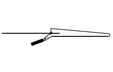
2m 2-element array - close-up (element folded)
The array is easy to carry as the elements can be 'telescoped in' and folded. Hence it lends itself to portable operation or direction finding.

Theoretical gain for this array is 3dB.

Preliminary on-the-air checks for gain, front-to-back ratio and null, were encouraging.

Related post: J-Pole Collinear for 2m
_______________________________

Homebrew RF Ammeter

This project is the result of recently reading WB8EVI - OM Mike Herman's article 'DIY RF Ammeter'.

An available aluminium baking tray, though a bit oversize, came in handy as an enclosure. A piece of aluminium sheet was used to coarsely fabricate a recessed cover.


Homebrew RF Ammeter
Trials were made using a 50Ω, 1mA FSD moving coil meter to display 1 RF Amp maximum. The RF toroid, picked up from the junk box, had no markings but its relative permeability was quite good for a 1:1 transformer to work. It measured OD 20mm, ID 12.5mm and H 12.5mm. Both the primary and the secondary were just wires passed through the toroid without winding.

Homebrew 1:1CT RF Ammeter - Schematic
In the final assembly, the primary was a piece of 18SWG solid bare copper wire soldered to the BNC sockets and the secondary a length of flexible insulated copper wire. A rubber grommet ensured positioning of the toroid. Wiring was on a piece of perfboard, supported directly on the meter terminals.

Calibration was done using a homebrew CW rig and a Weston 1.5A RF Ammeter, after which the variable resistor was replaced by 3 series-wired 10KΩ resistors.

Homebrew 1:1CT RF Ammeter - Inside view
Measurements with this RF Ammeter proved acceptable at 7 MHz, 14 MHz and also at 145 MHz!

However, the 1:1 transformer could cause the secondary load to be directly reflected as a series load in the feeder.  Also, the higher secondary current could result in overheating of the toroid and the 82 Ω resistor.

Hence it was decided to have 20 turns on the secondary side, thereby dropping the load ratio to 400 :1.

Homebrew 1:20 CT RF Ammeter - Schematic
The series load imposed on the feeder would now be in the region of only 0.1Ω.

The secondary was wound using solid hookup wire and the RF Ammeter rewired.

Homebrew 1:20 CT RF Ammeter - Inside view
Tests showed very good linearity at 7 and 14 MHz but drastic loss of sensitivity at 145 MHz!

Related post: Salvaged RF Ammeter
______________________________

Homebrew ¼ λ Magmount for 2m

Few parts are required to homebrew this magmount.

A 5¼” floppy disk drive rotor, with its boss removed, serves as the magnetic base. A thin plastic sticker, covering the exposed face of the magnet, prevents damage to the vehicle paint surface.

The enclosure is a suitably drilled Melamine or Bakelite cup on which the SO-239 is mounted.

2m ¼ λ Magmount details
RG-58/U or smaller coax is used. A ¼ λ counterpoise of stranded insulated hook-up wire is soldered to the braid of the coax. This is a must in case the rig is to be kept isolated from the body of the vehicle.

The enclosure is potted with epoxy to waterproof it and make it base-heavy. The same epoxy holds the assembly in position on the magnetic base.

The driven element is a ¼ λ length of 1.6mm brazing rod soldered to the PL-259 pin. The space between the PL-259 body and the driven element is filled with epoxy to prevent water ingress.

This magmount proved its usefulness on many occasions when access to the vehicle battery was denied and a separate battery had to be used.

Related post: Simple ¼ λ Ground Plane for 2m
______________________________

HT-powered CW Interface

A keyed piezo beeper, connected to the microphone jack of a HT, appeared feasible as a ready-made MCW generator.

It failed on 3 counts (high pitch, low volume and interrupted carrier) resulting in a very poor-quality signal.

Hence a bit of design effort was called for. The result is the following schematic.

HT-powered CW Interface - Schematic
It's a keyed audio oscillator, with a low part count, working off 4.5V - 1.5mA available at the microphone jack.

Oscillation is obtained using an AC128 (Germanium PNP AF transistor) and an audio transformer with a turns ratio of 1:5.

The 220K and 4.7K trimpots enable adjustment for the desired tone without motorboating.

In the event of the circuit failing to oscillate, connections to one of the transformer windings is reversed.

Connection to the microphone jack is through a shielded cable.

HT-powered CW Interface Board
The prototype was wired on a piece of perforated board with a microswitch serving as the PTT.

The unit was tested/adjusted while monitoring the signal with another rig. 100% modulation, with a clean note, was obtained.

Use of a homebrew electronic keyer precluded the need for a sidetone monitor.

It was an interesting weekend project using parts from the junk box.
______________________________

Direction-finding Yagi Beam for 70cm

The PVC pipe/brazing rod construction, used in homebrewing this antenna, is the brainchild of OM Nathan Loucks WB0CMT (A Portable 3-Element 2m Beam - April 1993 QST).

All it requires is a length of 25mm PVC pipe, 2 end caps, 1.6mm brazing rod, a BNC socket, a piece of RG-58U coax and M-Seal epoxy sealant.

70cm Direction-finding Yagi Antenna
Element lengths used:

Driven element: 330mm end-to-end, Director: 305mm, Reflector: 355mm

Element spacing:

Driven element to director: 130mm, Driven element to reflector: 75/85mm.

Conversion of the driven element, from a straight dipole to a half-folded one, was an afterthought to bring the SWR down to less than 1.5:1.

70cm Direction-finding Yagi - detail of driven-element
A length of 18SWG copper wire was used for the conversion.

Related post: Wire Slim Jim for 70cm
______________________________

'Wire Slim Jim' for 70cm

This Slim Jim for 70cm was homebrewed using a length of 18mm diameter thin-walled PVC tube, 20 SWG copper wire, a BNC socket and ‘M-Seal’(epoxy sealant in dual component lump form).

The wire ends and the flange-type BNC socket are secured with self-tapping screws.

Sealing against water ingress is done with M-Seal.

70cm Wire Slim Jim Antenna
A low SWR (less than 1.5:1) was obtained with the feed point at 25mm from the lower end.

This antenna weighs only 90 grams.

Related post: Open Stub J-Pole for 70cm
______________________________

A ¾ λ Ground Plane for 70cm

This antenna is my mast-mounted version of G2BCX OM F.C.Judd's design of a mobile
¾ λ collinear in his 'Two-metre Antenna Handbook'.

It is similar in construction to my ¼ λ Ground Plane for 70cm.

A ¾ λ Ground Plane for 70cm
A SO-239 connector is used.

The driven element, consisting of the ¼ λ lower portion, the ¼ λ hairpin stub and the ½ λ upper portion, is bent from a single brazing rod.

The blue plastic strut gives rigidity to the driven element.

SWR measured lower than 1.5:1 at 435 MHz.

Related post: Another ¼ λ Ground Plane for 70 cm
______________________________