Crystal Radio with a ferrite loopstick antenna

The local 200 kW, 612 kHz AM broadcast station, located 20 km away as the crow flies, is quite readable on this simple crystal radio employing a ferrite loopstick antenna (with its broadside oriented in the direction of  the station) and balanced-armature phones.

Ferrite loopstick antenna
The loopstick comprises 12 pieces of 4" long, 3/8" diameter ferrite rods stacked inside a 1½" diameter paper former.

Crystal radio with a ferrite
loopstick antenna - Schematic
The coil is 33 turns of PVC insulated copper wire (wire overall diameter 1/12"). It is tuned using a 500 + 500 pf variable capacitor with its sections connected in parallel.
_______________________________

Another Loop Antenna Crystal Radio

A heavy 2 m x 2 m floor-standing wooden showcase in the shack appeared to be suitable as a frame for a crystal radio loop antenna.  As luck would have it, the lone 20 km distant 612 kHz, 200 kW AM broadcast station being in the end-on position by default, there would be no need to move the unit. The  counter top would make it quite convenient to sit down and carry out the testing.

The 5 turn loop was easily wound using about 42 m of ordinary hook-up wire.

The shack is relatively quite small to get a photo of the actual unit.

Here's a representation of the same.

Makeshift 2 m x 2 m Square Loop Antenna
The shunt-fed circuit was wired first, using a 500 pF variable capacitor and a MBR 1060 Schottky rectifier found in the the junk box.

Shunt-fed Loop Antenna Crystal Radio - Schematic
The local station came in real loud through the balanced-armature phones. Headphone current, measured using a 1mA FSD 60 Ω meter, was 200 μA.

Next the series-fed circuit was tried out.  

Series-fed Loop Antenna Crystal Radio - Schematic
Reception was quite good, with the OA 79 diode delivering a headphone current of 100 μA.

A 14 turn 0.75 m x 0.75m loop antenna, wound with the same hook-up wire, yielded a headphone current of 100 μA when shunt-fed and 50 μA when series-fed. 

Related post: Loop Antenna Crystal Radio
_______________________________

Parallel-tuned Compact Loudspeaker Crystal Radio

Here are the schematics of two parallel-tuned versions of my 'Compact Loudspeaker Crystal Radio'.

Parallel - tuned Compact Loudspeaker
Crystal Radio - Schematic 1

Parallel - tuned Compact Loudspeaker
Crystal Radio - Schematic 2
The local 200 kW, 612 kHz AM broadcast station, just 20 km away, is heard quite well with either version on my 'Homebrew Horn Speaker'.

Related post: A Chance Crystal Radio Project
_______________________________

Tarnished Silver as a Crystal Radio Detector

A fully tarnished, shiny black silver artefact was tried out as a detector in place of the germanium transistor in my series-tuned, shunt-fed crystal radio.

Series-tuned Shunt-fed Crystal Radio - Schematic
Fortunately the presence of an untarnished spot facilitated the metal to metal connection.

A length of pencil 'lead' was used to probe the tarnished portion to locate the 'sweet spot'.

The local 612 kHz, 200 kW AM broadcast station, just 20 km away, was received quite well using a 60' wire antenna and balanced-armature phones. Headphone current, measured using a 1mA FSD 60 Ω meter, was 300 μA as compared to 750 μA with the germanium transistor and 50 μA with a razor blade as the detector. 

It was a confirmation of the shiny black tarnish being silver sulphide (a semiconductor).

A silver coin, stored in a plastic pouch and tarnished a dull grey, in its failure to detect, indicated that its tarnish was silver oxide (a good conductor of electricity).

Related post: Foxhole Radio Detector Variants
_______________________________

Carbon Microphone as a Crystal Radio Detector

A vintage telephone carbon microphone, which possesses multiple contacts between carbon granules and metal, was tried out as a detector, replacing the germanium transistor in my 
series-tuned, shunt fed crystal radio.

Vintage telephone carbon microphone

Series-tuned Shunt-fed Crystal Radio - Schematic
Its performance, after a bit of tapping, was as good as that of a razor blade detector (akin to moving the pencil or carbon contact on the razor blade to find the sweet spot).

Its performance improved considerably with a rundown button cell in series.

The carbon microphone behaviour was successfully simulated using two metal plates of size 8" x 8" x 1/16" with carbon granules salvaged from a discarded water filter.  

With one plate placed horizontally on the table, a thimbleful of carbon granules was distributed at the four corners and then sandwiched by the other plate. The top plate had to be moved to and fro to find the right spot.

During tests the signal strength was found to be fair with the specimen directly connected and very good with a rundown button cell connected in series with it.

_______________________________

A Chance Crystal Radio Project

A vintage unmarked inductor/transformer had been lying neglected in my junkbox for decades and I had to resurrect it.

Resistance checks showed that 2 windings, with a tap each, are terminated in its 6 pins. One measured 70 Ω with a 5 Ω tap and the other less than 1 Ω. A threaded core, with a movement of 5 mm is situated at the top of the unit.

The 70 Ω winding appeared to be suitable for a crystal radio. It was wired up as per the schematic shown below.

Chance Crystal Radio - Schematic
As luck would have it, the local 612 kHz, 200 kW AM broadcast station, situated 20 km away
(as the crow flies), comes in real loud using a 60' wire antenna and balanced-armature phones. Headphone current, measured using a 1mA FSD 60 Ω meter, is 250 μA with the core fully in and 300 μA with the core retracted.

The capacitive wire antenna series-tunes the link winding to resonance at 612 kHz, while the self-capacitance of the detector winding parallel-tunes it to resonance at the same frequency, as though the inductor/transformer has been tailor-made for this project.

Chance Crystal Radio
A cosmetic plastic jar makes a good base/enclosure for this chance crystal radio.

_______________________________

Pseudo FM Crystal Radio

After several failed attempts to build an FM Crystal Radio with a diode detector, a dual-gate mosfet version was tried out but also in vain.

The mosfet used was a 3N187 from the junk box.

FM Crystal Radio - Schematic
Now at a dead end, powering it up with a rundown 1.5 V button cell was the only way out. And it sprang to life!

Pseudo FM Crystal Radio - Schematic
A number of local stations were received.

Pseudo FM Crystal Radio
Notwithstanding the problems of hand effects and oscillations, it was music to my ears.

Pseudo FM Crystal Radio - Final schematic
The 330 μH moulded inductor was a later addition that solved the oscillation problem.

Pseudo FM Crystal Radio - Inside view
The factors contributing to my failure in building a real FM Crystal Radio could be the distance of the transmitters (6 km away as the crow flies) and their low power rating (1 to 10 kW).
_______________________________

A Tuned Passive Radiator

The problem with my 'Portable AM Crystal Radio' is that it works well only when close to an overhead CATV cable working as a passive radiator.

Hence it was decided to create a tuned passive radiator to further improve its performance.

One half of my 40 m inverted 'V' dipole antenna was chosen as the passive radiator. The series-tuned circuit was connected to the core of the coax at the shack end and earthed as shown.

Series-tuned Passive Radiator - Schematic

This setup enabled faint reception of the local 612 kHz 200 kW AM station on the portable crystal radio inside the shack.

After tuning the passive radiator to resonance, performance of the portable crystal radio was found to be quite good across the shack roof.

Identical performance was obtained when a parallel-tuned circuit was used.


Parallel-tuned Passive Radiator - Schematic

Related post: Portable AM Crystal Radio
_______________________________

Shortwave Crystal Radio

It was my first attempt at building a shortwave crystal radio.

Shortwave Crystal Radio
It's single-tuned and uses a 1N270 to drive vintage sound-powered phones.

The circuit was 'breadboarded' on an old fan regulator baseplate with the coil wound on a white plastic pill bottle.
Shortwave Crystal Radio - Schematic
A 2-section variable capacitor, with slow motion drive, was used for tuning. The 2 sections were connected in series for an effective maximum capacitance of 180 pF.

Using a 60' wire antenna and earth resulted in 'local strong medium wave station breakthrough' and hum.

With earth disconnected, the breakthrough and hum reduced considerably and it was possible to tune-in to a faint shortwave broadcast. It was from AIR Chennai, on 7380 kHz, located 270 km away.

Tuning further up, a weaker Oriental station was heard.

Severe fading was experienced with both the signals.

Similar results were obtained using a 1.5 m long telescopic antenna and earth.

On a later occasion the same stations came in louder, with no breakthrough and hum, using a 20 m inverted 'V' antenna.
_______________________________

Portable AM Crystal Radio

Here's the portable version of my 'Series-tuned Crystal Radio'.

Portable AM Crystal Radio
The prototype was wired on a piece of perforated board.

M0UKD's 'Loaded Quarter Wave Antenna Inductance Calculator' gave a loading coil inductance of the order of 10 mH at 612 kHz (the frequency of the 200 kW AM station located 20 km away). Hence two 4.7 mH moulded inductors were connected in series at the feed point, to resonate the 0.75 m long telescopic antenna at that frequency. 

Portable AM Crystal Radio - Schematic
At first nothing was heard even on the shack roof. However, on moving around, a favourable spot was found, where the reception is indeed quite good. The spot is close to an overhead CATV cable working as a passive radiator. The cable runs exactly in the direction of the station like a Beverage antenna.

Encouraged by the results, the final version was built using the plastic front panel of a discarded radio. In this version OA79 diodes were used with equally good results.

Portable AM Crystal Radio - final version
This radio works quite well, unaided by passive radiators, up to 5 km away from the transmitter.

Related post: A Tuned Passive Radiator
_____________________________

Minimalist UHF Crystal Radio

Here's the schematic of the minimalist version of my 'UHF Crystal Radio'.

Minimalist UHF Crystal Radio - Schematic
It was wired on a terminal block.

Using this simple setup, digital signals from the nearby cellphone tower were received on the shack roof.

Related post: Some thoughts on UHF Crystal Radios
_______________________________

Compact Loudspeaker Crystal Radio

This is the compact version of my 'Loudspeaker Crystal Radio'.

Compact Loudspeaker Crystal Radio
Trials on a number of assorted audio transformers, from the junk box, were not in vain. A push-pull output transformer, intended for a 1 W germanium transistor audio amplifier, gave excellent results.

Compact Loudspeaker Crystal Radio - Schematic
The centre-tap on the primary is not used.

A discarded blister pack serves as the base.

In spite of its small size, performance is as good as that of its counterpart.

My 'Homebrew Horn Speaker' and 60' wire antenna offer the perfect match for this crystal radio.

Related post: Alternative Detector for a Shunt-fed Crystal Radio
_______________________________

Makeshift Piezo Earphones

A makeshift piezo earphone arrangement comprises a stethoscope and a piezo transducer.

Stethoscope
The sound emanating from the transducer is captured by the bell of the stethoscope, held against its face.

Piezo Transducer
This arrangement was used while figuring out how to interface a piezo earpiece with a crystal radio. The transducer, a 1¾" telephone ringer, was salvaged from the junk box.
_______________________________

Series-tuned Moulded Inductor Crystal Radio

'A Series-tuned Air-core Coil Crystal Radio' and 'Another Series-tuned Air-core Coil Crystal Radio'  have been made simple by the use of moulded inductors instead of hand-wound coils.

Series-tuned Moulded Inductor Crystal Radio
This makes it possible to use a compact plastic cosmetic jar as a housing.

Moulded Inductor
There is no difference between the two with respect to performance. 

Series-tuned Moulded Inductor 
Crystal Radio - Schematic
Another Series-tuned Moulded
Inductor Crystal Radio - Schematic
The local 612 kHz, 200 kW AM broadcast station comes in real loud with a 60' wire antenna and balanced-armature phones. Headphone current, measured using a 1mA FSD 60 Ω meter, is 625 μA.

The performance of a parallel-tuned version is also quite good with a headphone current of 300 μA.

Parallel-tuned Moulded Inductor
Crystal Radio - Schematic
Related post: Another Series-tuned Air-core Coil Crystal Radio
______________________________

Another Series-tuned Air-core Coil Crystal Radio

This is the air-core coil version of my 'series-tuned crystal radio with alternative detector'.

Series-tuned Air-core Coil Crystal Radio
It is enclosed in a cosmetic jar with the 500 pF PVC gang condenser mounted inside its cap.

Series-tuned Crystal Radio - Schematic
There is sufficient clearance to close the jar even though the coil is wound on its body.

Series-tuned Crystal Radio - Coil view
The local 612 kHz, 200 kW AM broadcast station comes in real loud with a 60' wire antenna and balanced-armature phones. Headphone current, measured using a 1mA FSD 60 Ω meter, is 750 μA.

Related: 'Gibson Girl' Crystal Radio
_______________________________

'Gibson Girl' Crystal Radio

This series-tuned crystal radio was built using parts salvaged from a vintage / battered SCR - 578 lifeboat radio (popularly referred to as 'Gibson Girl').

The SCR - 578
It consists of a baseplate, antenna tuning coil, antenna tuning capacitor and terminal strip modified to suit.

'Gibson Girl' Crystal Radio
The only part required to be fished out from the junk box was a Schottky diode SB 860. It was mounted underneath the terminal strip.

'Gibson Girl' Crystal Radio - Schematic
The local 612 kHz, 200 kW AM broadcast station comes in real loud with a 60' wire antenna and balanced-armature phones. Headphone current, measured using a 1mA FSD 60 Ω meter, is 750 μA.

Related post: Series-tuned Ferrite Loopstick Crystal Radio
_______________________________

Loop Antenna Crystal Radio

A loop antenna crystal radio is of interest on account of its selectivity and portability. But, with respect to signal strength, it is no match for a crystal radio using an external vertical wire antenna and earth.

If signal strength could be considerably improved with increased loop size, then its portability would be compromised.

It may be configured as parallel-tuned or series-tuned.

1. Parallel-tuned version 

Parallel-tuned Loop Antenna Crystal Radio
2. Series-tuned version

Series-tuned Loop Antenna Crystal Radio
The loop antenna was rigged up using a 4-legged stool as a makeshift frame. The stool was laid on its side on the table, making it convenient to wind the loop on its legs.

4-legged stool as Loop Antenna frame
Both the versions were tested with the loop oriented end-on towards the local 612 kHz, 200 kW AM broadcast station.

Signal strength was the same with both, though a far cry from another crystal radio using a vertical wire antenna and earth.

Related post: Another Loop Antenna Crystal Radio
_______________________________

Current-operated 'S' Meter for a Crystal Radio

An 'S' meter, for a crystal radio with high-impedance phones, is generally a high-resistance microammeter connected across the phones. In other words, a sensitive voltmeter that does not bypass headphone current significantly.

Crystal Radio 'S' Meter
On the other hand, for a crystal radio with low-impedance phones, it's a low resistance microammeter connected in series with the phones. That is, a sensitive ammeter that does not drop headphone current significantly.

A voltmeter, discovered in my junk box, was used to build such a meter for my crystal radio which uses low-impedance balanced-armature phones.

Crystal Radio 'S' Meter - Schematic
On removing its series and shunt resistors, the resistance of the 1 mA FSD movement turned out to be only 60 Ω and hence quite suitable for the purpose. The existing graduations on the meter face were removed and replaced with graduations 0 -10 using a lead pencil.

The meter was already mounted on a square bakelite flange. The flange mounting holes served as terminal mounting holes, obviating the need for an enclosure.

The result - an interesting weekend project and a handy crystal radio test aid.

_______________________________

UHF Crystal Radio

A crystal radio was wired up to check for reception of VHF/UHF signals in the vicinity of the shack.

VHF / UHF Crystal Radio - Schematic
Using a gold bonded Germanium diode 1N65, a 500 mm whip antenna and balanced-armature phones, no signals were audible either in the shack or on the shack roof.

However, using a 250 mm whip, a weak digital signal was detected while moving on the shack roof. Position on the roof and direction in which the whip was pointed were quite critical.

It was presumed that the signals were from a nearby cellphone tower.

A 3 Element Yagi Beam for 33 cm was made using a broken snare drum stick for the boom and 20 SWG bare copper wire for the elements.

UHF Yagi Beam Crystal Radio  - Schematic
The coil was wound integral with the driven element. 

UHF Yagi Beam Crystal Radio
With this setup a higher signal strength was obtained.

A second Yagi Beam was then rigged up, with another diode providing the return path for the audio, instead of the coil.

UHF Yagi Beam Crystal Radio
with additional diode - Schematic
The signal strength was not as good. During trials, a chance shorting of  the first diode gave a considerable increase in signal strength.

Single-diode UHF Yagi Beam
Crystal Radio - Schematic
The diode and capacitor were hence discarded. Performance of this single-diode UHF crystal radio is quite good.
Single-diode UHF Yagi Beam Crystal Radio
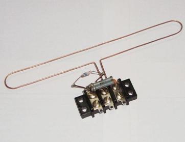
A folded dipole version, mounted on a terminal block, followed.

UHF Folded Dipole Crystal Radio - Schematic
It obviated the need for a coil / additional diode and worked quite well too.

UHF Folded Dipole Crystal Radio
The terminal block arrangement made it convenient to replace the folded dipole with a full wave loop.
UHF Full Wave Loop Crystal Radio
Likewise with an AWX antenna.

UHF AWX Antenna Crystal Radio
Results were as good as with the folded dipole.

Related post: Minimalist UHF Crystal Radio
_______________________________