After significantly improving the performance of
my first crystal radio using a series inductor, the focus was on a replacement for the OA5 which would give a higher output.
 |
| OA5 diode |
The base-emitter and base-collector junctions of germanium audio transistors like AC130, OC74, AC127, 2N61, AC188 and AD162 were tried out. However, they were all only as good as the OA5.
 |
| Germanium transistors |
As luck would have it, when the 2N61 was being tried out, an accidental short between its base and emitter leads resulted in a tremendous increase in signal strength. Hence the OA5 in the crystal radio was replaced with the base-emitter-shorted 2N61.
Using a wire antenna 60' long, the lone local 612 kHz, 200 kW AM broadcast station could now be heard even at a distance from the headphones! Headphone current measured using a 1mA FSD 60 Ω meter, was 725
μA.
 |
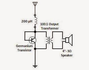
| Crystal Radio - Schematic |
The other transistors too gave identical results with their base and emitter leads shorted. Results with the base and collector leads shorted trailed close behind.
A dedicated unit of equal performance was built using a 3" x 3" x 1½" electrical bakelite box as an enclosure.
 |
| Series-tuned Crystal Radio Enclosure |
Screw terminals were attached on the rear for connecting the antenna, earth and headphones.
 |
| Inside the Series-tuned Crystal Radio |
Lugs on the screw terminals facilitated soldering of the transistor, moulded inductor and earth link.
When subsequent trials on series-fed crystal radios showed a degradation in their performance,
it was concluded that germanium transistors, with base/emitter interconnection, outperform germanium diodes only in shunt-fed crystal radios.
Related post: Current-operated 'S' Meter for a Crystal Radio
_______________________________